Robots can have their own body parts that have to be controlled
Logistics
- dynamaze
- cargo
- dashboard
- sort
- typist
- race
- convoy
- autopilot
- bowling
- guard
Final Projects
What is URDF?
- Uniform Robot Definition Format
- Defines a collection of links held together by joints
- Joints
- Are not “visible” - all they do is to show how two links move relative to each other
- See urdf documentation for all the details
- Links
- Are “visible”
- Can have many other properties
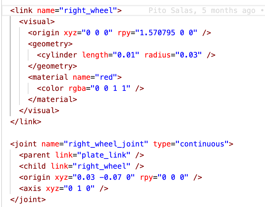
URDF Example
Joint Types
- revolute - a hinge joint that rotates along the axis and has a limited range specified by the upper and lower limits.
- continuous - a continuous hinge joint that rotates around the axis and has no upper and lower limits.
- prismatic - a sliding joint that slides along the axis, and has a limited range specified by the upper and lower limits.
- fixed - This is not really a joint because it cannot move. All degrees of freedom are locked. This type of joint does not require the axis, calibration, dynamics, limits or safety_controller.
- floating - This joint allows motion for all 6 degrees of freedom.
- planar - This joint allows motion in a plane perpendicular to the axis.
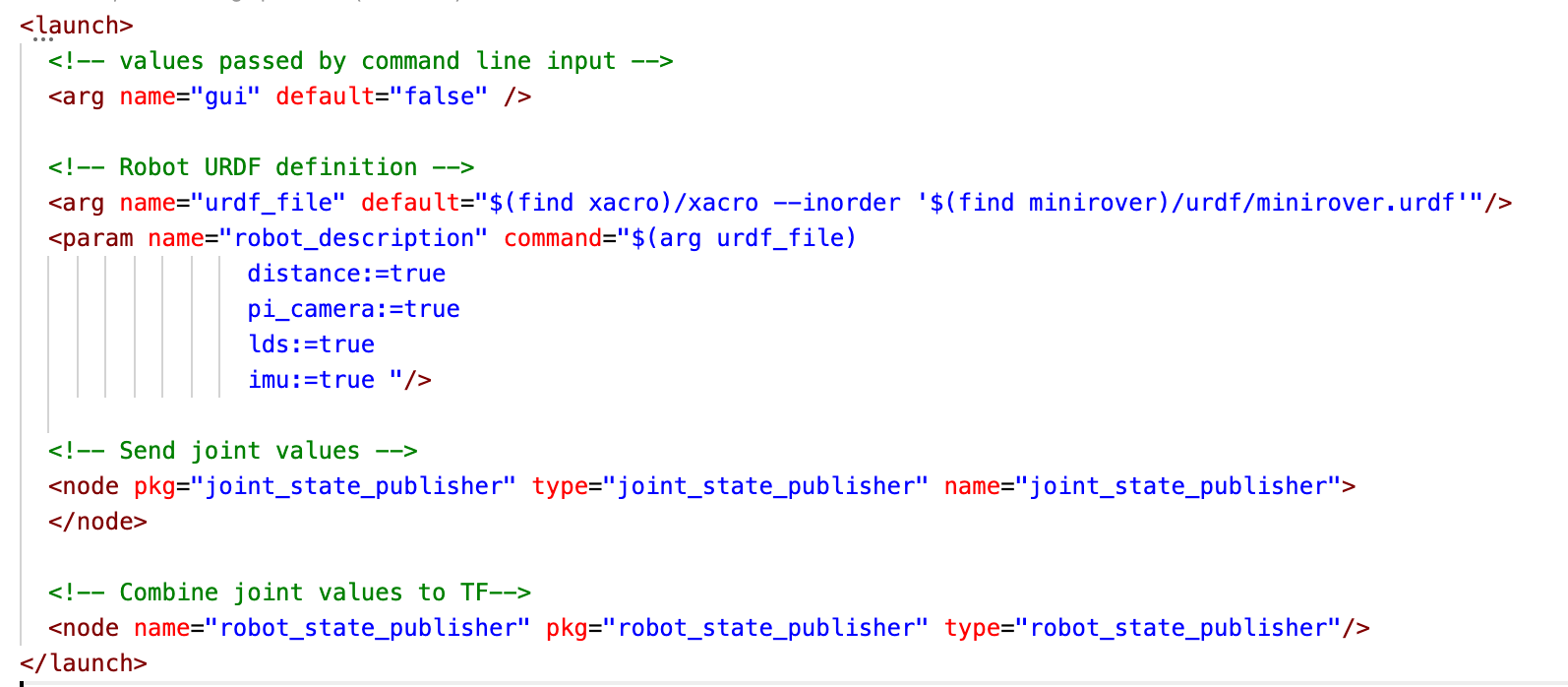
.launch file concerns
URDF Roles
- Describes geometry of a robot
- Names various links
- There are others
robot_state_publisher
- Looks at the urdf and publishes all the tfs which are statically tied to the base_link
- Using urdf, publishes
static_tf
joint_state_publisher
- Looks at dynamic links (those that can move) and updates the tf as they move
- What would cause them to move?
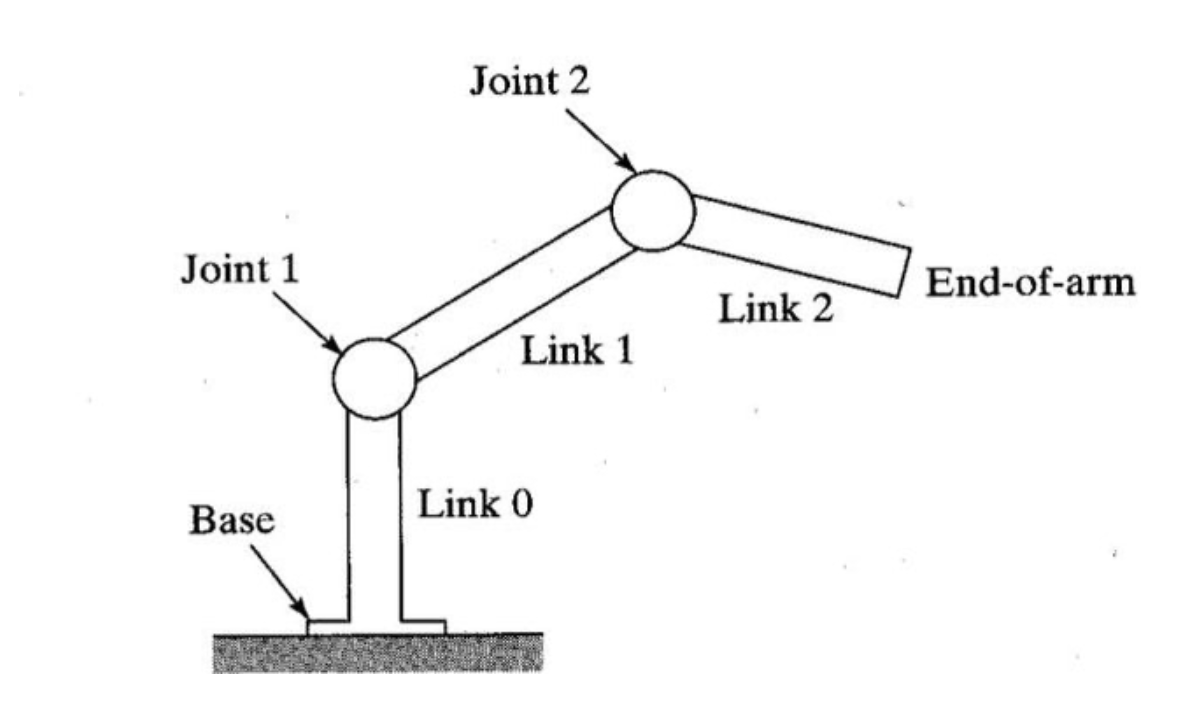
Manipulators
Kinematic Chains
- A set of links and joints together form a kinematic chain
- If one end is attached to something fixed (like the floor) it is “grounded”
- The other end will usually have some kind of gripper, sensor, or effector
- This system can be complex and can be analyzed mathematically
Coordinate Frames
- Ground based mobile robots have two important coordinate frames: the map and robot frames.
- Robot arms have many more coordinate systems.
- The links are fixed and of known length
- The joints are all in a known position represented by one or more angles
- Joint space and task space
- In ROS, names in URDF are used to name the frames
Kinematics
- Forward Kinematics
- If you set all the joint angles a certain way, where will the end be in space?
- This has a single solution and is tractable
- Reverse Kinematics
- If you want the end to be in a certain location, what should the joint angles be?
- This might have zero (out of reach), or more solutions
Charlie Arm

 (random Image from picsum.photos)